So I'm replacing my fuel tank on my P-39. The old one was a cylindrical beast made out of steel and set in a 3/4" plywood "box" frame, tabbed into the hull. Once the tank was out, the tabbing was surprisingly easy to remove because the wood was rotten and the tabbing was barely wet-out to begin with. A scraper and a small hammer was all it took to remove.
I have a new plastic tank and am now ready to construct the floors and stringers to support it. It is 30 gals. diesel (like the old one) except built to use the space better and allow me some extra room for a battery bank.
I'm looking to use the McMaster pre-fab'd square "pipe," which is 1/4" thick on all sides and 3" x 3" as floors and then use either more of this stuff for stringers on top of the floors, or use Biax with coosa board core.
It's getting a little too complicated for my taste, but it boils down to using the pre-fabed glass to save myself a lot of laminating over forms. I plan on laminating over most of it where I'll be tabbing of course. It will support roughly 250 lbs. rockin and rolling under the cockpit.
Without seeing any pictures, does anyone have an opinion on my plan? I can post some diagrams and pics once I get all this stuff to my web site.
cc
Pre-made FRP board PART II
-
Ceasar Choppy

- Boat Obsession Medal Finalist
- Posts: 622
- Joined: Thu Mar 09, 2006 11:05 am
- Location: Port Starboard, MD
-
Tim

- Shipwright Extraordinaire
- Posts: 5708
- Joined: Tue Apr 01, 2003 6:39 pm
- Boat Name: Glissando
- Boat Type: Pearson Triton
- Location: Whitefield, ME
- Contact:
Without really knowing the specifics, offhand I'd say the concept sounds fine. The prefab FRP is certainly a lot stronger than what you took out of there.
Remember that the plastic tank will require more support directly beneath, since it isn't as self-supporting as the heavy steel.
Remember that the plastic tank will require more support directly beneath, since it isn't as self-supporting as the heavy steel.
---------------------------------------------------
Forum Founder--No Longer Participating
Forum Founder--No Longer Participating
-
Hirilondë
- Master of the Arcane
- Posts: 1317
- Joined: Thu Dec 28, 2006 8:50 am
- Boat Name: Hirilondë
- Boat Type: 1967 Pearson Renegade
- Location: Charlestown, RI
Hmmm, no pictures? I shouldn't even be replying till they are up!
Off-hand it sounds more than strong enough. Depending on how well you can tab some of the framing to the hull you could probably bolt the FRP to it and maybe even some of the framing to itself.
Off-hand it sounds more than strong enough. Depending on how well you can tab some of the framing to the hull you could probably bolt the FRP to it and maybe even some of the framing to itself.
Dave Finnegan
builder of Spindrift 9N #521 'Wingë'
--------------------------------------------------------------------------------------------------------------------------------------------------------------------
Gresham’s Law of information: Bad information drives out good. No matter how long ago a correction for a particular error may have appeared in print or online, it never seems to catch up with the ever-widening distribution of the error.
-
Ceasar Choppy
- Boat Obsession Medal Finalist
- Posts: 622
- Joined: Thu Mar 09, 2006 11:05 am
- Location: Port Starboard, MD
Ok OK... Let me try and get something up. I gotta digitize the drawings.
OK, here is the full description: http://www.pearson39.org/fueltank.html
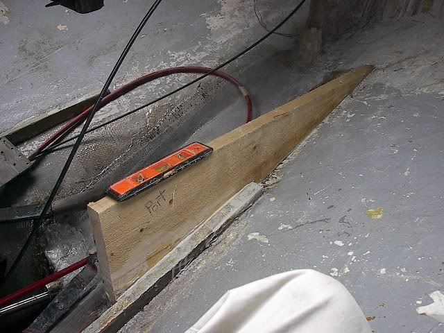
Here is just a pic of what I'm talking about. Visualize the curves of the hull. :)

Thanks!
OK, here is the full description: http://www.pearson39.org/fueltank.html
Here is just a pic of what I'm talking about. Visualize the curves of the hull. :)
Thanks!
-
Ceasar Choppy
- Boat Obsession Medal Finalist
- Posts: 622
- Joined: Thu Mar 09, 2006 11:05 am
- Location: Port Starboard, MD
-
Ceasar Choppy
- Boat Obsession Medal Finalist
- Posts: 622
- Joined: Thu Mar 09, 2006 11:05 am
- Location: Port Starboard, MD
It is actually not that bad. It is actually gi-nor.. (nevermind, you hate that word!).
I've been in and out of there so many times, I've got my boat-yoga down pretty well. The other nice thing is that since most of the old tabbing came right up, I won't have to do a lot of grinding to prep for the new.
Getting good pics of the area is hard because there is no good spot to get a full view.
My main concern was avoiding sharp corners. I was originally going to do this with two "U" shaped "floors" using cheap foam and lots of fiberglassing over them... but that plan had a lot more corners! The other problem is that the tank actually sits quite high in the front (still at the waterline), but it would have taken a lot of glasswork to support it properly I thought. The hull down there is wide and steep as it is where that big skeg is attached. In fact I can see where the foam for the skeg was poured in. See the pics here: http://www.pearson39.org/fueltank.html
I'm so ready to get this done and get back in the water!
-
Ceasar Choppy
- Boat Obsession Medal Finalist
- Posts: 622
- Joined: Thu Mar 09, 2006 11:05 am
- Location: Port Starboard, MD
-
Ceasar Choppy
- Boat Obsession Medal Finalist
- Posts: 622
- Joined: Thu Mar 09, 2006 11:05 am
- Location: Port Starboard, MD


-
Ceasar Choppy
- Boat Obsession Medal Finalist
- Posts: 622
- Joined: Thu Mar 09, 2006 11:05 am
- Location: Port Starboard, MD
Sure.
It is 30 gal polyPROPYLENE 3/8" thick which was nitrogen welded and fabricated by Triple M Plastics up in Kennebunk, ME.
I couldn't find anything comparable for a crosslinked Polyethylene rotomolded tank which I would probably prefer, but Triple M has done tanks for me before, are reputable, and I've been very happy with them.
Here's the diagram I did for them:
-
Ceasar Choppy
- Boat Obsession Medal Finalist
- Posts: 622
- Joined: Thu Mar 09, 2006 11:05 am
- Location: Port Starboard, MD
-
Ceasar Choppy
- Boat Obsession Medal Finalist
- Posts: 622
- Joined: Thu Mar 09, 2006 11:05 am
- Location: Port Starboard, MD
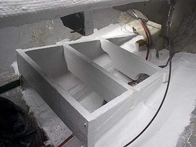
So, I'm getting closer on this project and am excited that I've recovered enough space to store my batteries in all one bank just forward of the fuel tank. See the link to my site above with updated pictures.
One of the problems I faced was access to the rear of the engine (or front-- it is turned around because of a v-drive). I needed to get in a 30 gal. tank, batteries and a waterlift all in the space underneath the cockpit of my P-39. IT IS A LARGE AREA... but not as large as you might think once everything gets put in.
Anyway, by using the prefabed 2" square FRB tube (0.25" thick) as stringers, and taking Hirolande's suggestion of using bolts to attach this stuff, I will be able to unbolt the cornered pieces once the batteries are removed to allow for any access I will need to the engine.
Well that is certainly alot more excotic than mine.Looks good so far. I just used 2X6" Cypress glued with epoxy to the hull and then glassed in with Vinylester and two layers of 24 oz. Biax. I then just primed and painted with an oil based paint. For the top I just used 1/2" ply with two layers of Biax on top and one on the bottom(Vinylester). I used a piece of foam to make a template for the stringers.
-
Ceasar Choppy
- Boat Obsession Medal Finalist
- Posts: 622
- Joined: Thu Mar 09, 2006 11:05 am
- Location: Port Starboard, MD
Looks good stone!
If you had seen both the amount, and state, of the wood I pulled out of that area you would know why I was avoiding wood. The one picture doesn't show the 3 garbage bags of rotten stringy wood I pulled out.
Off today to make the final fit of the fuel tank and hopefully install the batteries.
If you had seen both the amount, and state, of the wood I pulled out of that area you would know why I was avoiding wood. The one picture doesn't show the 3 garbage bags of rotten stringy wood I pulled out.
Off today to make the final fit of the fuel tank and hopefully install the batteries.