Previous Situation
I had previously been going to re-wire the whole boat, based on things like this:

(six conductors artfully braided together and wrapped in lots of black tape!)
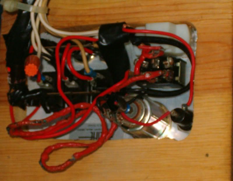
(see the melted/burnt insulation from previous electrical fires?)

(Spaghetti-O's all over the battery)
Question
Anyway, all that stuff is history - I've got the previous owner's wiring removed, and the idea is just to hook up the basic system the way the boat was built in the first place. This seemed very simple - a panel with three rockers, and three square pushbuttons, each marked "fuse".

Two parts of this I get:
1) There's a positive bus that the switches are bonded to, and there are leads on the back of the switches that go to the lighting circuits
2) Inside the box (not on the panel) is a block of four fuses, which are on the negative side. These are jumpered together on one side, and have separate leads to the individual circuits on the other.
One other part, I think maybe I get, but I'm not sure:
1) There's another bus connecting the three square pushbutton rigs that are marked "fuse". Each of these is jumpered to one of the rocker switches. One end of this second bus is connected to the negative side of the fuse array, and the other end has a separate lead to the other end of one of the individual fuses.
Anyway, I have been getting very odd results, and I don't understand how the square "fuse" buttons fit into the picture. Are they "push to test", i.e. they bypass the fuse so you can tell if it's blown?