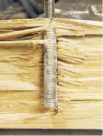
keelbolts wrote: The problem comes whenever you run a fastener into end grain wood.
That was the thing I had "wondered" about. It was more of a casual question, but since engine vibration basically consists of jumping up and down, that force is 'trying' to pull the bolts out all the time.
I don't know enough about timber and plywood to make a practical assessment, it's the edge-on, end-grain that I got a funny feeling about.
jhenson wrote:Duncan,
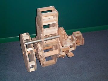
I have thought of using studs inbedded in the beds, but I sort of want to keep from that idea right now. I seems to me to be a nice feature to remove the eight bolts and have the ability to slide the engine forward past the bridge deck, secure the lifting eye, and remove it. Again, I may be over thinking this thing.
I ran into a bit of a snag yesterday when I went to order the threaded inserts that Tim used on the Triton Daysailor. The supplier is out of stock, and I'm told that they will probably no longer be available.
I think the idea of removable studs is a great one - Murphy's Law, and all that. What if you overdrill and epoxy the hole? Wax the stud, thread a nut on the bottom end of it, and put the assembly in the hole to cure. The next day, you double-nut the stud and out it comes.
In this way, your nut at the bottom becomes the "threaded insert". I'm guessing that the slug of epoxy in the hole should also make a stronger bearing surface than the plywood itself. It should seep into the wood a bit , too, which ought to make the whole thing stronger? I suppose you might be able to find longer nuts or bigger ones, too (or even use several), so that you'd be just as well off as with the 'threaded insert'?
A friend of mine did this to mount the autopilot ram on a big boat - it's not the same thing as engine mounts, but I think the principle is fairly similar.
I think the primary purpose of the metal bar on top is more to spread the impact of the vibration over the whole top surface of the bed. This seems like a good idea, and threading/tapping it wouldn't hurt, but I am guessing that having nuts "embedded in the bed" with epoxy would be a pretty solid mounting point?