Old electrical panel

Ask a question...get an answer (or two).
Post Reply
Duncan
Candidate for Boat-Obsession Medal
Posts: 388
Joined: Fri Mar 03, 2006 7:28 am
Boat Name: Coquine
Boat Type: Cape Dory 27
Location: Montréal
Contact:

Old electrical panel

Post by Duncan »

I promised the new owner running lights and cabin lights for when he picks up the Westwind on Sunday morning.

Previous Situation

I had previously been going to re-wire the whole boat, based on things like this:

Image

(six conductors artfully braided together and wrapped in lots of black tape!)
Image

(see the melted/burnt insulation from previous electrical fires?)

Image

(Spaghetti-O's all over the battery)

Question

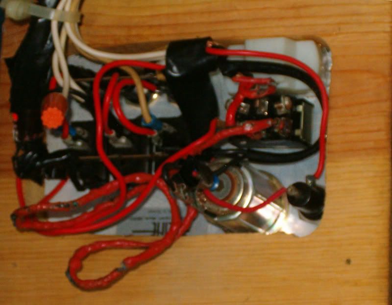
Anyway, all that stuff is history - I've got the previous owner's wiring removed, and the idea is just to hook up the basic system the way the boat was built in the first place. This seemed very simple - a panel with three rockers, and three square pushbuttons, each marked "fuse".

Image

Two parts of this I get:
1) There's a positive bus that the switches are bonded to, and there are leads on the back of the switches that go to the lighting circuits
2) Inside the box (not on the panel) is a block of four fuses, which are on the negative side. These are jumpered together on one side, and have separate leads to the individual circuits on the other.

One other part, I think maybe I get, but I'm not sure:
1) There's another bus connecting the three square pushbutton rigs that are marked "fuse". Each of these is jumpered to one of the rocker switches. One end of this second bus is connected to the negative side of the fuse array, and the other end has a separate lead to the other end of one of the individual fuses.

Anyway, I have been getting very odd results, and I don't understand how the square "fuse" buttons fit into the picture. Are they "push to test", i.e. they bypass the fuse so you can tell if it's blown?

Image
Cape Dory 10 & 27
User avatar
Tim
Shipwright Extraordinaire
Posts: 5708
Joined: Tue Apr 01, 2003 6:39 pm
Boat Name: Glissando
Boat Type: Pearson Triton
Location: Whitefield, ME
Contact:

Post by Tim »

A photo showing the back of your panel would be most descriptive here.

However, in general, it sounds like:

1. Power (hot lead) to your panel should be connected to the side of the fuse block that's jumpered together (thereby energizing the entire fuse block). Then, individual hot leads should run from the other side each fuse to the appropriate rocker switch.

2. There's no negative side to a fuse array. The fuses are to be installed inline in the positive (hot) lead for each circuit; that's your overcurrent protection in your case. Each fuse should be appropriately sized for the wire size and the circuit (generally 15A).

3. Somewhere there has to be a negative distribution buss, which will contain all your grounds. The negative lead from the battery also connects to this buss. Depending on the number of circuits, this can be a single stud, or a multiple stud buss. You can have up to four conductors on a single stud. IS the second buss you mentioned acting as a negative distribution?

4. The other buss bar may also have been installed previously so that multiple leads could be run through the minimal number of three switches and fuses. I'm not quite sure based on your description. Again, you can install no more than 4 conductors on a single terminal stud.

5. How many circuits do you have in total? More than three?

6. What is that silver rocker switch at the bottom of the panel? And the thing to the left of it?

I may be misunderstanding what you're describing; my comments are general in nature and are subject to modification based on additional information about your specific setup.
---------------------------------------------------
Forum Founder--No Longer Participating
Ryan
Skilled Systems Installer
Posts: 223
Joined: Wed Aug 17, 2005 2:14 pm
Location: NE GA

Post by Ryan »

Tim wrote:
6. What is that silver rocker switch at the bottom of the panel? And the thing to the left of it?
It looks to be an old "battery charge" meter with a momentary Battery A/Battery B switch to change the battery the meter is connected to. Just a guess though.
LazyGuy
Candidate for Boat-Obsession Medal
Posts: 349
Joined: Mon Jun 11, 2007 9:31 pm
Boat Name: Paper Moon
Boat Type: Luders 33 (Allied Boat Co.)
Location: Mystic CT

Post by LazyGuy »

Duncan,

It appears you have a switch and fuse set up. The lead from the battery switch (Hot) goes to the buss. The buss, as you described, is connected to the switch. From the switch, there should be a short jumper wire to one fuse. Then from the other side of the fuse to the light(s). As stated above, you should set the fuse based on the wire size first then the load. 14 AWG wire is good to 15 amps but if, based on the size of the electrical load you use a 5 amp fuse that is ok. If you use a 20 amp fuse, you may end up with the same thing you removed.

The return wire from the lights should be tied together and attached to the negative side of the battery.

From the pictures, you would be wise to nuke every piece of wiring and start over. There should be a maximum of three wires on each side of the battery. The positive side connects to the battery switch, the bilge pump (through a fuse) and the VHF radio (if one is aboard). Anything else should be wired to the battery switch.
Cheers

Dennis
Luders 33 "Paper Moon" Hull No 16

Life is too short to own an ugly boat.
Duncan
Candidate for Boat-Obsession Medal
Posts: 388
Joined: Fri Mar 03, 2006 7:28 am
Boat Name: Coquine
Boat Type: Cape Dory 27
Location: Montréal
Contact:

Post by Duncan »

Progress (I think). I found the same panel on an internet search, and the manufacturer posted wiring instructions.

Image

http://www.sea-dog.com/422310.html

It turns out the separate fuse block has nothing to do with the panel, which makes things much easier. The square "Fuse" buttons are what I had originally thought - pop-out fuse holders. (They wouldn't pop out, though, which is why I asked if they were some kind of "push-to-test" rig). The manufacturer's website, however, shows that you need to push something small in the side to release them.

Apart from this, I guess most of the confusion was the lack of a negative bus, plus the mess made by previous attempts to splice in extra circuits.

Still not quite sure about the bracket with the four other fuses, but I have a pretty good idea now - unswitched circuits for the cabin lights, macerator and so on. I am optimistic that some progress may be made this afternoon, thanks for the comments!
Image
Cape Dory 10 & 27
LazyGuy
Candidate for Boat-Obsession Medal
Posts: 349
Joined: Mon Jun 11, 2007 9:31 pm
Boat Name: Paper Moon
Boat Type: Luders 33 (Allied Boat Co.)
Location: Mystic CT

Post by LazyGuy »

Double post. Sorry.
Last edited by LazyGuy on Sat Oct 06, 2007 12:29 pm, edited 2 times in total.
LazyGuy
Candidate for Boat-Obsession Medal
Posts: 349
Joined: Mon Jun 11, 2007 9:31 pm
Boat Name: Paper Moon
Boat Type: Luders 33 (Allied Boat Co.)
Location: Mystic CT

Post by LazyGuy »

Duncan,

Thanks for the clarification. I thought the fuses you were talking about were the fuses that are part of the panel. If you keep the extra fuse block, I would preferably power all the fuses from one rocker switch through one 10 or 15 amp fuse. Second choice would be directly from the feed from the on/off/both switch in parallel with the switch panel. Not directly connected to the battery.

As you no doubt already know, each circuit, including the bilge pump, needs a fuse. Even if it is 15 or 20 amps.

Good luck!
Cheers

Dennis
Luders 33 "Paper Moon" Hull No 16

Life is too short to own an ugly boat.
Duncan
Candidate for Boat-Obsession Medal
Posts: 388
Joined: Fri Mar 03, 2006 7:28 am
Boat Name: Coquine
Boat Type: Cape Dory 27
Location: Montréal
Contact:

Post by Duncan »

whoops, double-posted here, too.
Last edited by Duncan on Sun Oct 07, 2007 7:47 pm, edited 1 time in total.
Image
Cape Dory 10 & 27
Duncan
Candidate for Boat-Obsession Medal
Posts: 388
Joined: Fri Mar 03, 2006 7:28 am
Boat Name: Coquine
Boat Type: Cape Dory 27
Location: Montréal
Contact:

Post by Duncan »

Thanks for the tips and time and attention. Things went well, despite working against time with an anxious new owner hovering over me.

I did the switched circuits according to the panel wiring diagram (of course!). The jumpered-together side of the additional fuse block worked out well as a negative bus.

I didn't connect any unswitched circuits (other than the VHF, straight off the battery, with an inline fuse), but if I had, I would have used another positive buss for them.

One lesson I have learned is not to spend any time analyzing and puzzling over someone else's wiring (unless they were decent enough to provide a diagram). I wasted a lot of time scratching my head over the previous stuff. Once I got fed up and plunged in with a plan of how things should go, however, things started moving right along!
Image
Cape Dory 10 & 27
Post Reply